To take advantage of the DC response of VC MEMS accelerometers, the readout device must be in a DC coupled state. If a signal conditioner is used for power it should also be DC coupled. Consult the appropriate manufacturer or product manual for specific details. Since most PCB VC MEMS accelerometers contain a built-in voltage regulator, they may also be powered from other power sources and handle a wide voltage range without adversely affecting performance. Consult individual product specifications for acceptable excitation voltages and additional powering details. Because VC MEMS accelerometers can measure static (constant) acceleration, the DC offset voltage will be affected by the positional alignment relative to the Earth’s gravity. When the sensitive axis of the accelerometer is not aligned with gravity, the output will equal the zero-g offset voltage on the PCB calibration certificate. If the sensitive axis of the accelerometer is aligned with gravity, the output will be equal to the bias voltage plus 1g of output. Figures 2 and 3 show sensor orientation examples.
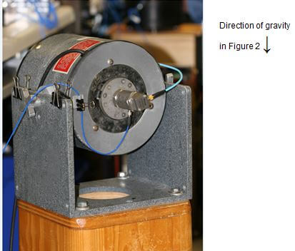
Figure 2. Sensor/sensitive axis not aligned with gravity (zero-g output condition)
Figure 3. Sensor/sensitive axis mounted in +1g output condition with respect to Earth’s gravity
The electronics inside VC MEMS sensors contain a voltage regulator. This allows the sensor to be powered by any unregulated DC voltage source. PCB® offers signal conditioner models 482C27 (4-channels) and 483C28 (8-channels) as VC MEMS power sources. Other acceptable power units include automotive or marine batteries, DC voltage laboratory supplies and low-voltage PC board voltage supplies. The cable shield needs to be terminated at one end to ensure ground loops are not induced.