General Piezoelectric Theory

To generate a useful output signal, our sensors rely on the piezoelectric effect. ("Piezo" is a greek term which means "to squeeze.") When the piezoelectric elements are strained by an external force, displaced electrical charge accumulates on opposing surfaces. Figure 1 illustrates the displacement of electrical charge due to the deflection of the lattice in a naturally piezoelectric quartz crystal. The larger circles represent silicon atoms, while the smaller ones represent oxygen. Crystalline quartz, either in its natural or high-quality, reprocessed form, is one of the most sensitive and stable piezoelectric materials available.

In addition to quartz crystals, PCB also utilizes man-made, polycrystalline, piezoceramics. These materials, which are forced to become piezoelectric by the application of a large electric field, produce an extremely high charge output. This characteristic is ideal for use in low-noise measurement systems. Other advantages / disadvantages are listed in Table 1, where a comparison of each piezoelectric material is shown.

Quartz Crystal Polycrystalline Ceramic
naturally piezoelectric material artificially polarized, man-made material
high voltage sensitivity high charge sensitivity
stiffness comparable to steel unlimited availability of sizes and shapes
exhibits excellent long term stability materials available which operate at 1000 F (540 C)
non-pyroelectric output due to thermal transients (pyroelectric)
low temperature coefficient characteristics vary with temperature

Table 1: Comparison of Piezoelectric Materials


Many different sizes and shapes of piezoelectric materials can be used in piezoelectric sensors. Acting as true precision springs, the different element configurations shown in Figure 2 offer various advantages and disadvantages. (The red represents the piezoelectric crystals, while the arrows indicate how the material is stressed. Accelerometers typically have a seismic mass, which is represented by the gray color. A more complete description of sensor structures is given in the next section.) The compression design features high rigidity, making it useful for implementation in high frequency pressure and force sensors. Its disadvantage is that it is somewhat sensitive to thermal transients. The simplicity of the flexural design is offset by its narrow frequency range and low overshock survivability. The shear configuration is typically used in accelerometers as it offers a well balanced blend of wide frequency range, low off axis sensitivity, low sensitivity to base strain and low sensitivity to thermal inputs.


Figure 2: Material Configurations

With stiffness values on the order of 15E6 psi (104E9 N/m2), which is similar to that of many metals, piezoelectric materials produce a high output with very little strain. In other words, piezoelectric sensing elements have essentially no deflection and are often referred to as solid-state devices. It is for this reason that piezoelectric sensors are so rugged and feature excellent linearity over a wide amplitude range. In fact, when coupled with properly designed signal conditioners, piezoelectric sensors typically have a dynamic amplitude range (ie: maximum measurement range to noise ratio) on the order of 120 dB. This means that a single accelerometer can measure acceleration levels as low as 0.0001 g's to as high as 100 g's!

A final important note about piezoelectric materials is that they can only measure dynamic or changing events. Piezoelectric sensors are not able to measure a continuous static event as would be the case with inertial guidance, barometric pressure or weight measurements. While static events will cause an initial output, this signal will slowly decay (or drain away) based on the piezoelectric material or attached electronics time constant. This time constant corresponds with a first order high pass filter and is based on the capacitance and resistance of the device. This high pass filter ultimately determines the low frequency cut-off or measuring limit of the device.

A representation of a typical force, pressure and acceleration sensor is shown in Figure 3. (The gray color represents the test structure. The blue color corresponds to the sensor housing. The piezoelectric crystals are colored red. The black electrode is where the charge from the crystals accumulates before it is conditioned by the yellow, micro-circuit. The accelerometer also incorporates a mass which is shown by the green color.) Note that they differ very little in internal configuration. In accelerometers, which measure motion, the invariant seismic mass, 'M', is forced by the crystals to follow the motion of the base and structure to which it is attached. The resulting force on the crystals is easily calculated using Newton's Second Law of Motion: F=MA. Pressure and force sensors are nearly identical and rely on an external force to strain the crystals. The major difference being that the pressure sensors utilize a diaphragm to collect pressure, which is simply force applied over an area.


Figure 3: Sensor Construction

Because of their similarity, sensors designed to measure one specific parameter are also somewhat sensitive to other inputs. By minimizing their sensitivity to unwanted events, sensors can more accurately measure their intended parameter. For instance, sophisticated pressure sensors often utilize a compensation element to reduce its sensitivity to acceleration. Other sensors employ thermal compensating amplifiers to reduce the sensors overall thermal coefficient. Finally, accelerometers utilize alternative shear-structured sensing elements to reduce the affects of thermal transients, transverse motion and base strain.

After the sensing element produces a presumably desirable output, this signal must be conditioned prior to being analzyed by the oscilloscope, analyzer, recorder or other readout device. As shown in Figure 4, this signal processing can be accomplished by two different methods: (1) internal to the sensor by a microelectronic circuit; or, (2) external to the sensor in a "black box". (PCB uses the registered trademark ICP® to denote sensors which include built-in microelectronics. Sensors without electronics are typically referred to as charge mode sensors.)


Figure 4: Sensor Systems

These analog processing circuits serve the same general functions which include: (1) conversion to a useful, low impedance, voltage signal; (2) signal amplification / attenuation; and (3) filtering. However, it is important to note that the location of the circuit may be critical to the proper operation of the sensing system. A more detailed description of each method follows.

The ICP® sensor will be discussed first. This concept has experienced a large degree of technical improvements since its advancement in 1967. That is, the circuits have become smaller, the component prices have dropped and the signal processing capabilities have increased as a result of miniature integrated circuits and mirco hi-meg resistors. Even with these improvements, the original intent of the idea remains unchanged...simplicity and ease of use. This two-wire system uses a common conductor for power / signal and an additional conductor for the signal ground. The built-in circuits are miniature charge or voltage amplifiers depending on the sensing element type. Power to these components typically comes from an 18 to 30 VDC, 2 mA constant current supply. (Aside from price, convenience and/or features, there is no technical advantage from having a constant current power source which is external or built-in to the readout device.) A detailed system schematic is shown in Figure 5.
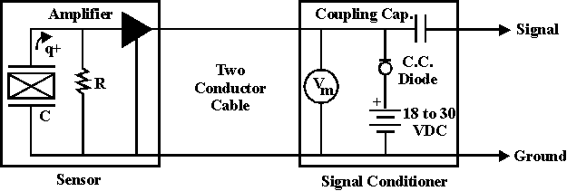


Figure 5: ICP® Sensor System

The characteristics of this system include: (1) built-in microelectronics produce a low impedance, voltage signal compatible with most readout equipment; (2) requires only a simple, easy to use constant current signal conditioner which results in a lower per channel cost; (3) signal is capable of being transmitted over long cables through harsh environments with no loss in signal quality; (4) operating temperature of circuit typically limited to 250 F (121 C) or sometimes 325 F (154 C); (5) functions with ordinary two-conductor coaxial or twisted pair cables; and (6) characteristics of sensor (sensitivity & frequency range) are fixed within the sensor and are independent of supply voltage.

Charge mode sensors utilze the same mechanical sensing structure as do ICP® sensors, however, the signal processing electronics are placed externally. Since integrated, micro-circuits had not yet been developed, the first piezoelectric sensors, which were developed in the 1950's, operated under this principal. These charge systems were often difficult to operate properly and were traditionally expensive as a result of the sophisticated external charge amplifier. (Alternative, lower cost in-line devices are becoming more popular.) Today, charge mode sensors are typically only used in environments where the temperature prohibits the use of sensors with built-in electronics.

As would one might expect, charge mode systems offer various advantages and disadvantages which include: (1) sensor outputs a high impedance signal which requires conditioning prior to being analyzed; (2) requires external signal conditioner (laboratory charge amplifier, in-line source follower, etc...); (3) high impedance signal has the potential to be contaminated by environmental influences such as cable movement, electro-magnetic signals and radio frequency interference; (4) since electronics are external, certain models are capable of operation up to 1000 F (540 C); (5) requires special low-noise cabling; and (6) characteristics of sensor (sensitivity & frequency range) are variable and can be ranged by switching components in the external signal conditioner.

Piezoelectric sensors offer unique capabilities which are typically not found in other sensing technologies. As discussed, there are certain advantages (such as wide frequency and amplitude range) and disadvantages (no static measuring capability) depending on the particular application. Therefore, when choosing a specific sensor or sensor technology, it is important to pay close attention to the performance specifications.